As an Amazon Associate, this site earns commissions from qualifying purchases. For more details, click here.
An inverter can provide your home with continuous power. You can never tell when a power failure will occur and for how long, so having a backup supply is ideal. If you have always wanted to buy and install an inverter, the question that probably comes up a lot is the wiring. How does it work and how many is required? In this guide we will answer those questions.
Inverters have connections for the battery and your home electrical system, so no need for separate wires. The only time you will need separate wiring is if you install multiple batteries.
The easiest way to explain how this works is to show you how to install an inverter at home. The following is a general overview of the steps, but you should check the instruction manual that came with your inverter.
This video shows how the installation is done. If you would like step by step instructions, read on.
How to Wire an Inverter
Note: this guide assumes you have experience handling electrical wires. If not, leave this task to a licensed electrician. This guide is applicable for most inverters even those up to 10000 watts.
Step 1 Set up the Inverter
The inverter should be placed far from any flammable or combustible objects. The location must not have any direct sunlight or moisture. An inverter may be installed horizontally or vertically depending on the type.
Step 2 Connect the Inverter Wiring to the Battery
Connect the positive inverter wire to the positive battery terminal. Next, connect the negative wire on the negative terminal. The positive wire is red and the negative wire is black.
What inverter wire size do you need? Most inverters use 4 AWG wires like these made by WindyNation. The thinner the wire the greater the resistance, so choose thicker wires. Your inverter manual will indicate what wire thickness is required.
Step 3 Connect Inverter Wire to AC Power
Your inverter has three output wires, positive (red), negative (green) and earth (black). Sometimes the earth wire is green and the negative is black. Check your inverter manual as it has the color coding information for the wires.
- Connect the red (positive) wire to the main MCB (miniature circuit breaker). The main MCB is the one with the fuses and the switches.
- For the green (negative) wire, connect it to the negative MCB wire.
- Connect the earth inverter wire to the MCB earth.
Step 4 Connect Appliance Wiring to the Inverter
Connect the wire from the inverter AC output to a circuit breaker. You will find an open breaker on the main electrical panel of your home.
To run a load (appliance), connect the appliance wiring to the breaker. Make sure the breaker is not overloaded.
Inverters have a mains input so you can connect it to the main power supply. If you check the main electrical panel you will see branches for handling various power loads. What you do is choose the branch that you want to be powered by the inverter.
In simple terms, you go from the main circuit breaker to the circuit breaker branch, to the inverter and its load / appliance. Each of these requires its own wiring.
There are only three wires you have to connect. The one from the inverter to the battery, the wire from the switchboard to the inverter and from the AC output. The AC cable is what is used to connect and run appliances.
What Inverter Wire Size Do You Need?
The battery wire size depends on the inverter load capacity. 12 800-1500W inverters will need 2-4 AWG wires. Most inverters already come with wires, so you will know what size to get. The battery wire should be at last 24 inches long.
If the inverter is less than 800 watts, AWG 6 is ideal. Again, inverters usually include the battery cable so you do not have to compute the gauge wire. Knowing is still essential though just in case you have to replace the wire.
If you are going to use a 3000W Renogy inverter, the minimum AWG wire size is 3/0. The higher the gauge wire size, the less chances the system overheats. While smaller wire sizes are cheaper they are not suitable for larger inverters. In fact it can damage not just the wire but the inverter too.
12V inverter Wire Size Guide
| Inverter Rating | AWG Wire Size |
|---|---|
| 100-450W | 3 |
| 450-600W | 2 |
| 600-900W | 2 |
| 900-1500W | 2/0 |
| 1500-3000W | 3/0 |
24V inverter Wire Size Guide
| Inverter Rating | AWG Wire Size |
|---|---|
| 100-450W | 8 |
| 450-600W | 4 |
| 600-900W | 2 |
| 900-1500W | 2/0 |
| 1500-3000W | 4/0 |
48V inverter Wire Size Guide
| Inverter Rating | AWG Wire Size |
|---|---|
| 900-1500W | 2/0 |
| 1500-3000W | 3/0 |
| 3500-6000W | 4/0 |
No matter what inverter you are using, you should always account for the watt capacity, the AWG wire size, the wire amp rating and the continuous watts. The amp rating tells you how much currant the wire can safely hold, while continuous watts refers to the voltage lost from the battery to the inverter.
Do I Need to Wire an Inverter to a Circuit Breaker?
A circuit breaker is necessary to prevent overloading among other uses. Without a breaker, the wire between the battery and inverter is a potential fire hazard.
Another benefit of a circuit breaker is that it works well with a solar powered home. When installed you can connect appliance and electronic devices to a power outlet and use them.
If you are setting up a solar system for your home, make sure the distance between the solar panels and battery is correct . Once your solar power system is ready, you can connect the inverter to the circuit breaker.
If you want step by step instructions, follow this.
Step 1
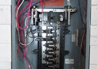
Shut off the inverter and the main power switch on the circuit breaker. This switch is in the center of the panel near the top.
Step 2
Remove the screws on the circuit breaker front panel. Choose which circuit you want to hook up with your solar panel system. You will make this connection with the inverter. Use a screwdriver to remove the panel backside.
Step 3
Hook up the wire to the inverter output. Before doing this you have to make certain of two things. One, the inverter is designed to work with circuit breakers, and two, the wire size is correct.
Most inverters run fine with circuit breakers so this should not be a problem. Check the inverter manual for the suggested wire size. It will depend on the amperage capacity and the inverter voltage.
Step 4
Once the wire is connected, you should conduct a test. Get a voltmeter and place its probes on the bus bar. If there is voltage, check the circuit breaker because it is probably still on.
If the breaker is off and there is still a voltage rating, contact an electrician as there is power coming from somewhere. But if there is no voltage, proceed to step 5.
Step 5
Strip half an inch from the insulation covering the ends of the inverter wire going into the circuit breaker. Look for the neutral ground in the breaker and connect the white wire to it. Hook up the hot wire (black or red) to the breaker you chose.
Put the screws back on the circuit breaker panel. Switch on the circuit breaker main power. Turn the inverter on. Now you can test outlets plugged into the circuit for your solar power configuration.
The instructions in this post assume that you have experience handling electrical wires. If you do not, please hire an electrician to do it for you. Inverters have a lot of safety features and installation has been simplified, but the risks in handling electricity and wires are always present.
This is true not just for inverter installation but also connecting the inverter to the main line. As shown here, this requires working with the circuit breaker. If you are not sure what to do, consult an electrician.

I am an advocate of solar power. Through portablesolarexpert.com I want to share with all of you what I have learned and cotinue to learn about renewable energy.